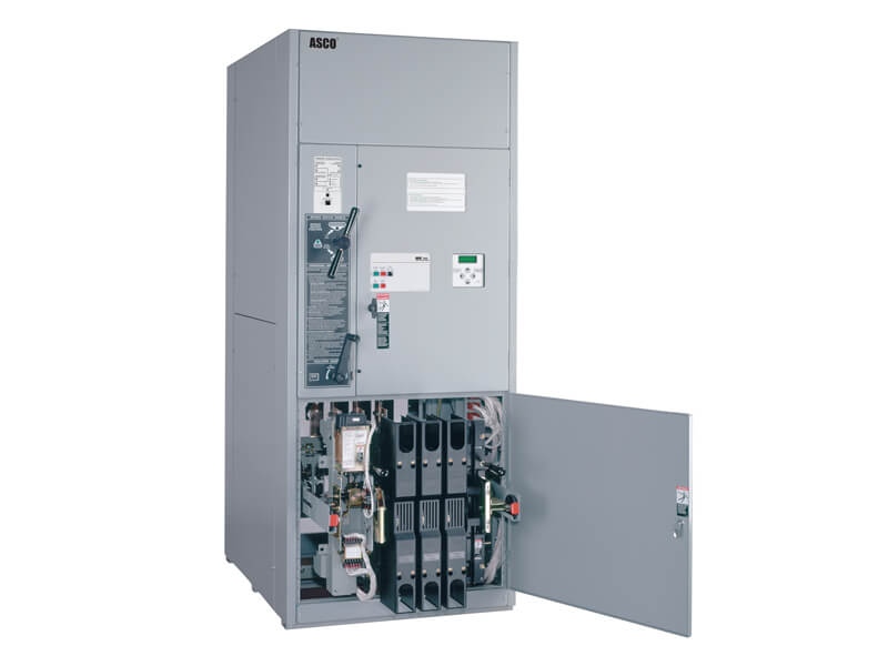
Chapter 6 of NFPA 110 defines the performance requirements for transfer switches. Transfer switches allow the Emergency Power Supply (EPS) (i.e. genset) to assume the electrical load from the primary power source (i.e. utility) during a power outage. There are two types of transfer switches.
- Manual switches require the operator to physically operate the switch to transfer the electric load from one power source to the other.
- Automatic transfer switches (ATSs) are the most common style of switches used in Emergency Power Supply Systems (EPSSs) and automatically transfer the load to the EPS when the normal source of power is lost and back again to the normal source once the power has returned.
Automatic Transfer Switches
For most applications where NFPA 110 would apply, an automatic transfer switch (ATS) is used to transfer load from a primary source of supply to an engine generator set. ATS’s use undervoltage-sensing devices to monitor the primary source of power. The ATS:
- Automatically senses an interruption to the normal source of power
- Triggers controls to start the generator set
- Transfers the load to the generator after it has reached the proper voltage and frequency, typically within 5-10 seconds
- Continues to monitor utility power during the outage
- Switches the load from the generator back to the normal source after normal power is restored
- Shuts down the generator after a cool down period
NFPA 110 requires that each switch shall be listed for emergency service as a completely factory-assembled and factory-tested apparatus. (6.1.6). NFPA 70, National Electric Code (NEC) also requires that transfer switches used for emergency systems and rated 1000 VAC and below be listed for emergency system use. It is not necessary to use switches listed for emergency service to transfer loads not designated as emergency.
ATS’s are available in a wide range of ampacities and types from a variety of manufacturers who can provide NFPA 110 complaint switches. ATS’s transfer load from one power source to another by opening and closing contacts that are connected to the primary power supply and the backup power source. Different configurations are available depending on the application including:
- Open Transition – break before make transfer; used in emergency, code-required and optional standby applications with resistive loads or small motor loads.
- Closed Transition – make before break transfer; for critical power applications, such as hospitals and data centers.
- Delayed Transition – timed center off or time delay to neutral; for inductive (motor) loads and recommended by some manufacturers of UPS and VFD equipment.
- Soft Load Transition – synchronizes the generator set to the normal utility power
- Bypass Isolation– allows the ATS to be serviced without disrupting power; for critical power and maintenance requirements.
- Service Entrance – incorporates a utility circuit breaker disconnect in the ATS; fully rated and UL listed for use as "service entrance" equipment.
NFPA 110 requires mechanical interlocking or an approved alternate method to prevent the inadvertent interconnection of the primary power supply and the EPS, or any two separate sources of power. (6.2.3) An open transition switch uses break before make sequence of operation to prevent inadvertent interconnection and power is interrupted for approximately 40 milliseconds. Certain applications may use closed-transition or soft-load transition switching, which allows momentary paralleling of the generators with the utility. Closed transition switching is used in applications where the interruption of power even for a few milliseconds is not acceptable (e.g. hospital operating rooms). However, this equipment should be approved by the local utility and the authority having jurisdiction (AHJ).
NFPA 110 also requires that transfer switches be equipped with time-delay devices, engine generator exercising timers, a test switch, and other controls and indicators to allow safe and reliable operation. (6.2) NFPA 110 Chapter 8: Routine Maintenance and Operational Testing specifies that time delays for ATS’s shall be set as follows:
- Time delay on start:
- 1 second minimum
- 0.5 second minimum for gas turbine units
- Time delay on transfer to emergency: no minimum required
- Time delay on restoration to normal: 5 minutes minimum
- Time delay on shutdown: 5 minutes minimum
For a more complete understanding of transfer switch equipment, see our Technical Articles, download the ASCO White Paper: ATS Selection Basics, or Contact Us to schedule a Lunch and Learn or speak with one of our application engineers.
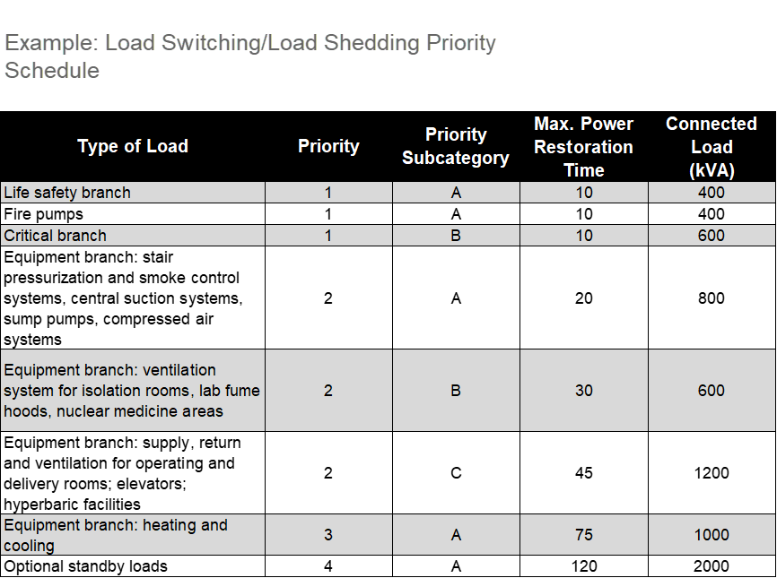
Load Switching (Load Shedding)
NFPA 110 requires that when two or more generators are paralleled for emergency power, the paralleled system must be arranged to prevent the connection EPS-damaging loads. (6.3) Section 6.3.3 requires that the transfer of loads shall be sequenced as follows:
- First priority loads, such as emergency loads, shall be switched to the emergency bus upon sensing the availability of emergency power on the bus (within 10 seconds)
- Legally required standby loads follow the emergency loads (within 60 seconds)
- Last priority are the optional standby loads
Each time an additional generator set is connected to the bus, a remaining load shall be connected in order of priority until all standby loads are connected to the bus. The system shall also be designed so that, upon failure of one or more engine generator sets, the load is automatically reduced (shed), starting with the load of least priority so that the last load affected is the highest priority or emergency load.
Connecting loads in sequence using multiple ATSs with proper time delays can reduce starting requirements on the EPS and can potentially reduce the size of the generator set. Setting time delays while staying within the required time required for power restoration by the Type of EPSS can also help generators to stabilize voltage and frequency.

Bypass-Isolation Switches
Bypass-isolation switches feature a redundant secondary manually operated switch that routes power from the source to the distribution system without passing through the transfer switch. The primary purpose of a bypass-isolation switch is to allow safe access for inspecting, maintaining, or servicing the switch without interrupting power to critical loads.
When selecting ATS’s, consideration should be given to the effect that load interruption could have on a load during maintenance and service of the transfer switch.
For more information on bypass-isolation switches, download the ASCO White Paper: Application and Design Factors for Automatic and Bypass-Isolation Switches (Part 1 and Part 2)
Protection
NFPA 110 requires that overcurrent protective devices (OCPD) are coordinated to optimize selective tripping of the OCPD when a short circuit occurs. (6.5) It is important that the various OCPDs be coordinated, as far as practicable, to isolate faulted circuits and to protect against cascading operation on short circuit faults. A short-circuit and selective coordination study would need to be performed by a qualified engineer to determine the maximum available short-circuit current at the service and all switchboards, panels, and transfer switches.
.png)


